
Voice Over IP Device
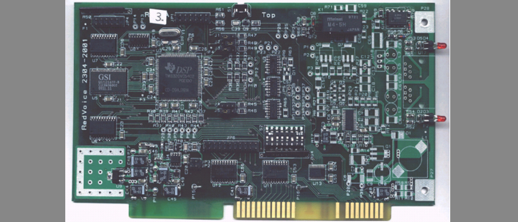
The “Voice over IP” device connects the telephone line to PC and allow usual phone calls over the Phone Lines or performs phone calls over the Internet Network.
Technical Specifications:
1) Physical Connections
- PHONE Device Port: RJ-11, 2 wire;
- PSTN Line Port: RJ-11, 2 wire;
- ISA Bus Card
2) Specifications:
- Full-duplex audio
- 16 digit DTMF decoding and generation
- Voice compression for minimal audio delay
- Audio sample rate at 10kHz
- Line Echo-Cancellation
- Auto gain control
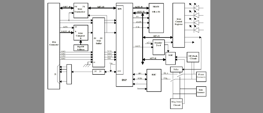
○ The ISA interface contains the ISA connector an 8-bit data transceiver connected to the Host Port Interface of DSP. The 8-bit address comparator selects the device, and the 8-bit buffer performs the 5volt to 3.3volt level conversion.
○ The Digital Signal Processor (“TMS320C5402”) performs the followings main functions: the Device Management, Audio Coding, and Eco Canceller.
TMS320C5402 Overview:
CPU
– Advanced multibus architecture (Harvard; one program bus, three data
buses, and four address buses)
– 40-bit arithmetic logic unit (ALU), including a 40-bit barrel shifter and
two independent 40-bit accumulators
– 17-bit × 17-bit parallel multiplier coupled to a 40-bit dedicated adder
for nonpipelined single-cycle multiply/accumulate (MAC) operation
Internal Memory
-Program ROM – 4K, DualAccessRAM – 16k
Instruction set
– Instructions with a 32-bit long operand
– Instructions with 2- or 3-operand simultaneous reads
– Arithmetic instructions with parallel store and parallel load
On-chip peripherals
– On-chip phase-locked loop (PLL) clock generator with internal oscillator
or external clock source. With the external clock source, there are
several multiplier values – until x16.
– 2x Multichannel buffered serial port (McBSP)
– Direct memory access (DMA) controller (6x Channels)
– Enhanced 8-bit Parallel Host-Port-Interface (HPI8)
– 2x Programmable timer
Speed
– 3.3/1.8-V power supply device with speeds up to 100 MIPS (10-ns
instruction cycle time)
Emulation
– Boundary Scan – IEEE Standard 1149.1 boundary scan logic
– Boot Loader on chip
The Power-Management, Reset and Watch-Dog-Timer functions are achieved by an external circuit “TPS3305”.
○ The application programs are stored in an external memory type “GS71216TP”-GSY Technology (64Kx16 Asynchronous Static RAM memory, 8.9ns access time).
○ The Subscriber Line Interface Circuit, SLIC-“SI3210” performs the interface with the phone line. In this part there are also circuits for the detection of the “off-hook” state and “ring-detect” on phone line.
○ The Relay Circuit performs the commutation of the telephone to the phone line or to the SLIC in order to transfer the voice data flows through PC (via DSP microcontroller to PC-ISA interface).